Circuits
We develop notebooks for analysis of Hardware Commissioning (HWC) tests and events during operation (FPA).
1. RB – Main Dipole Circuit
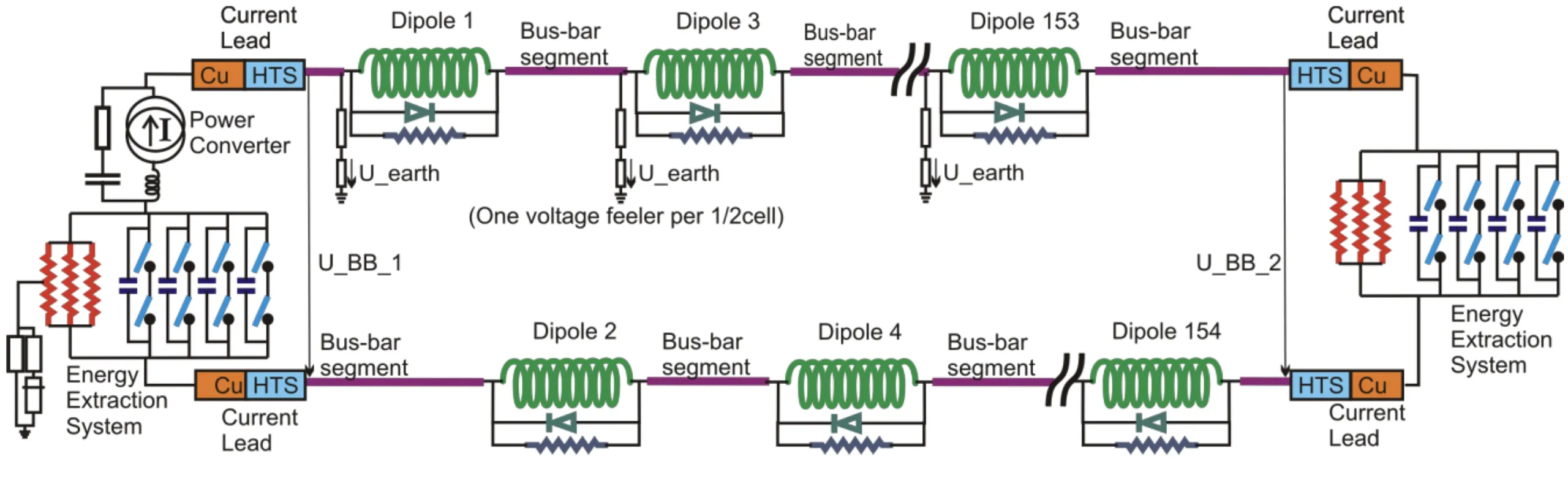
source: Powering Procedure and Acceptance Criteria for the 13 kA Dipole Circuits, MP3 Procedure, https://edms.cern.ch/document/874713/5.1
| Type | Test | Current | Description | Notebook | Example report |
| HWC | PIC2 | I_MIN_OP | Interlock tests with PC connected to the leads | AN_RB_PIC2 | AN_RB_PIC2 |
| HWC | PLI1.a2 | I_INJECTION | Current cycle to I_INJECTION | AN_RB_PLI1.a2 | AN_RB_PLI1.a2 |
| HWC | PLI1.b2 | I_INJECTION | Energy Extraction from QPS | AN_RB_PLI1.b2 | AN_RB_PLI1.b2 |
| HWC | PLI1.d2 | I_INJECTION | Unipolar Powering Failure | AN_RB_PLI1.d2 | AN_RB_PLI1.d2 |
| HWC | PLI2.s1 | I_INTERM_1 | Splice Mapping | AN_RB_PLI2.s1 | AN_RB_PLI2.s1 |
| HWC | PLI2.b2 | I_INTERM_1 | Energy Extraction from PIC during the ramp | AN_RB_PLI2.b2 | AN_RB_PLI2.b2 |
| HWC | PLI2.f1 | I_INTERM_1 | Quench heater provoked | AN_RB_PLI2.f1 | AN_RB_PLI2.f1 |
| HWC | PLIM.b2 | I_SM_INT_4 | Energy Extraction from QPS | AN_RB_PLIM.b2 | AN_RB_PLIM.b2 |
| HWC | PLIS.s2 | I_SM | Splice Mapping | AN_RB_PLIS.s2 | AN_RB_PLIS.s2 |
| HWC | PLI3.a5 | I_INTERM_2 | Current cycle to I_INTERM_2 | AN_RB_PLI3.a5 | AN_RB_PLI3.a5 |
| HWC | PLI3.d2 | I_INTERM_2 | Unipolar Powering Failure | AN_RB_PLI3.d2 | AN_RB_PLI3.d2 |
| HWC | PNO.b2 | I_PNO+I_DELTA | Energy Extraction from QPS | AN_RB_PNO.b2 | AN_RB_PNO.b2 |
| HWC | PNO.a6 | I_PNO | Energy Extraction from QPS | AN_RB_PNO.a6 | AN_RB_PNO.a6 |
| Operation | FPA | I_PNO | FPA during operation with magnets quenching | AN_RB_FPA | AN_RB_FPA |
2. RQ – Main Quadrupole Circuit
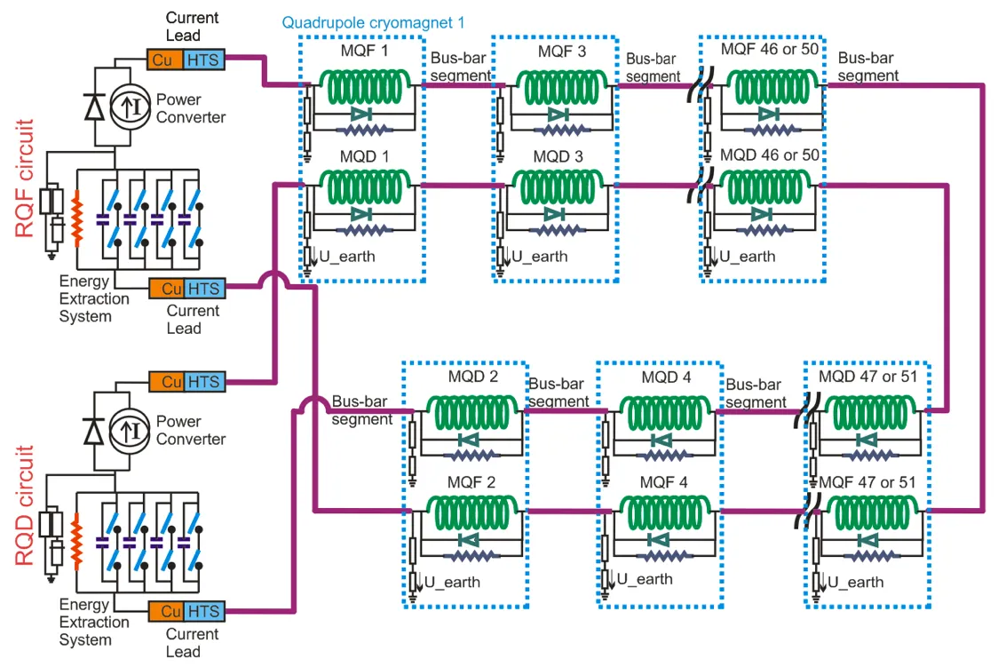
source: Test Procedure and Acceptance Criteria for the 13 kA Quadrupole (RQD-RQF) Circuits, MP3 Procedure, https://edms.cern.ch/document/874714/5.1
| Type | Test | Current | Description | Notebook | Example report |
| HWC | PIC2 | I_MIN_OP | Powering Interlock Controller | AN_RQ_PIC2 | AN_RQ_PIC2 |
| HWC | PLI1.b3 | I_INJECTION | Energy Extraction from QPS | AN_RQ_PLI1.b3 | AN_RQ_PLI1.b3 |
| HWC | PLI1.d2 | I_INJECTION | Unipolar Powering Failure | AN_RQ_PLI1.d2 | AN_RQ_PLI1.d2 |
| HWC | PLI2.s1 | I_INTERM_1 | Splice Mapping | AN_RQ_PLI2.s1 | AN_RQ_PLI2.s1 |
| HWC | PLI2.b3 | I_INTERM_1 | Energy Extraction from QPS | AN_RQ_PLI2.b3 | AN_RQ_PLI2.b3 |
| HWC | PLI2.f1 | I_INTERM_1 | Heater Provoked Quench | AN_RQ_PLI2.f1 | AN_RQ_PLI2.f1 |
| HWC | PLIM.b3 | I_SM_INT_4 | Energy Extraction from QPS | AN_RQ_PLIM.b3 | AN_RQ_PLIM.b3 |
| HWC | PLIS.s2 | I_SM | Splice Mapping at I_SM | AN_RQ_PLIS.s2 | AN_RQ_PLIS.s2 |
| HWC | PLI3.a5 | I_SM, I_INTERM_2 | Current cycle to I_INTERM_2 | AN_RQ_PLI3.a5 | AN_RQ_PLI3.a5 |
| HWC | PLI3.b3 | I_INTERM_2 | Energy Extraction from QPS | AN_RQ_PLI3.b3 | AN_RQ_PLI3.b3 |
| HWC | PNO.b3 | I_PNO+I_DELTA | Energy Extraction from QPS | AN_RQ_PNO.b3 | AN_RQ_PNO.b3 |
| HWC | PNO.a6 | I_PNO | Current cycle to I_PNO | AN_RQ_PNO.a6 | AN_RQ_PNO.a6 |
| Operation | FPA | I_PNO | FPA during operation with magnets quenching | AN_RQ_FPA | AN_RQ_FPA |
3. IT – Inner Triplet Circuits
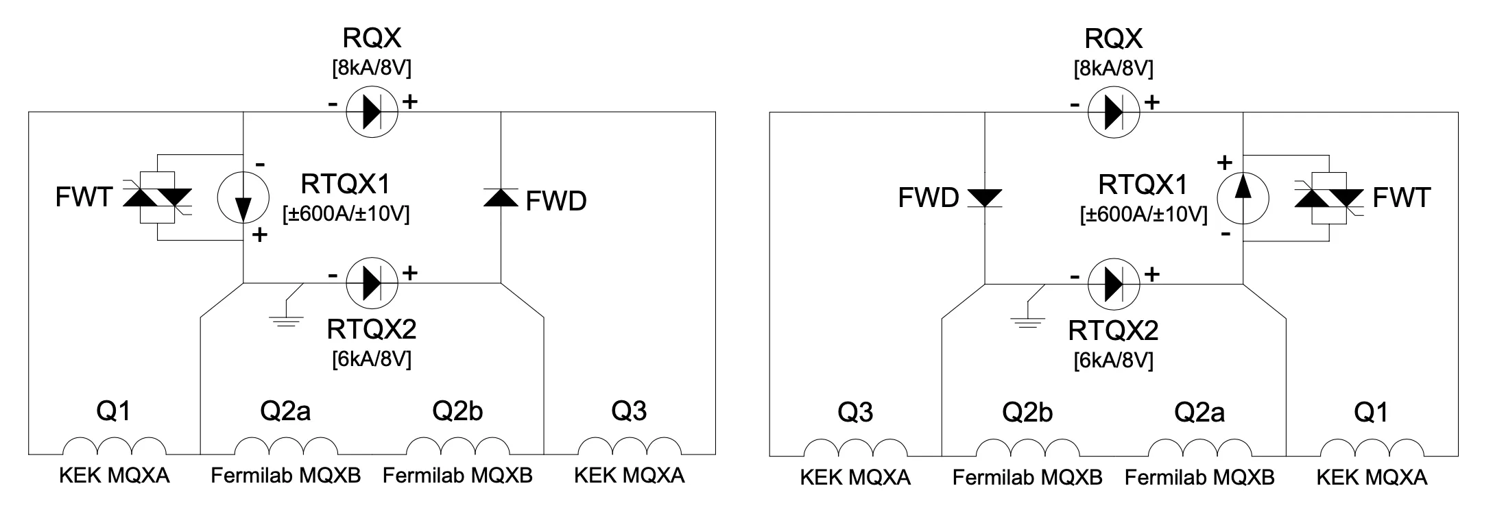
| Type | Test | Current | Description | Notebook | Example report |
|---|---|---|---|---|---|
| HWC | PCC.T4 | ~ | Power Converter Configuration part 2 | AN_IT_PCCT4 | – |
| HWC | PIC2 | ~ | Powering Interlock Controller check with standby current | AN_IT_PIC2 | AN_IT_PIC2 |
| HWC | PNO.D12 | 10% of I_PNO | Powering Failure at +10% of nominal current | AN_IT_PNO.d12 | – |
| HWC | PNO.D13 | 10% of I_PNO | Powering Failure at -10% of nominal current | AN_IT_PNO.d13 | – |
| HWC | PLI3.F6 | I_PLI3 | Heater Discharge Request at 2nd intermediate current (Note that I_RTQX1=0A | AN_IT_PLI3.f6 | AN_IT_PLI3.f6 |
| HWC | PNO.D14 | 50% of I_PNO | Powering Failure at +50% of nominal current during a SPA | AN_IT_PNO.d14 | AN_IT_PNO.d14 |
| HWC | PNO.D15 | 50% of I_PNO | Powering Failure at -50% of nominal current | AN_IT_PNO.d15 | AN_IT_PNO.d15 |
| HWC | PNO.A9 | I_PNO+I_DELTA | Training and plateau at nominal current | AN_IT_PNO.a9 | AN_IT_PNO.a9 |
| HWC | PNO.D16 | 90% of I_PNO | Powering Failure at +90% of nominal current | AN_IT_PNO.d16 | AN_IT_PNO.d16 |
| HWC | PNO.D17 | 90% of I_PNO | Powering Failure at -90% of nominal current | AN_IT_PNO.d17 | AN_IT_PNO.d17 |
| Operation | FPA | I_PNO | FPA during operation with magnets quenching | AN_IT_FPA | AN_IT_FPA |
source: Test Procedure and Acceptance Criteria for the Inner Triplet Circuits in the LHC, MP3 Procedure, https://edms.cern.ch/document/874886/2.1
4. IPQ (Individually Powered Quadrupoles)
- 2MQM
Apertures B1 of 2 magnets are powered in series with one power supply.
Apertures B2 of 2 magnets are powered in series with second power supply.
The return bus is common for both power circuits.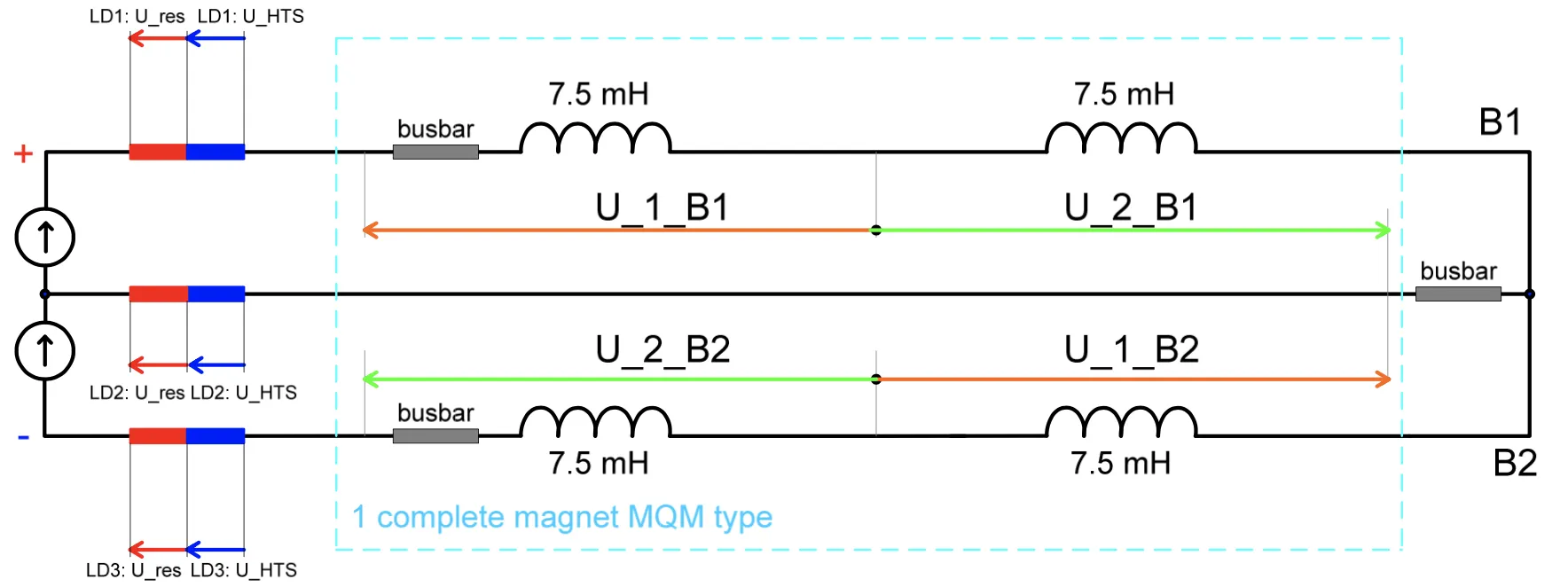
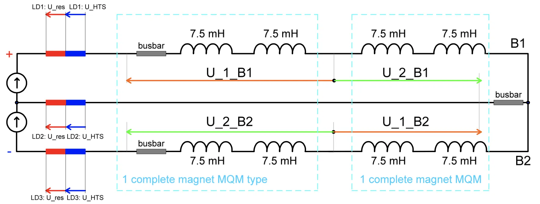
- 2x2MQM
Apertures B1 of 4 magnets are powered in series with one power supply.
Apertures B2 of 4 magnets are powered in series with second power supply.
The return bus is common for both power circuits.
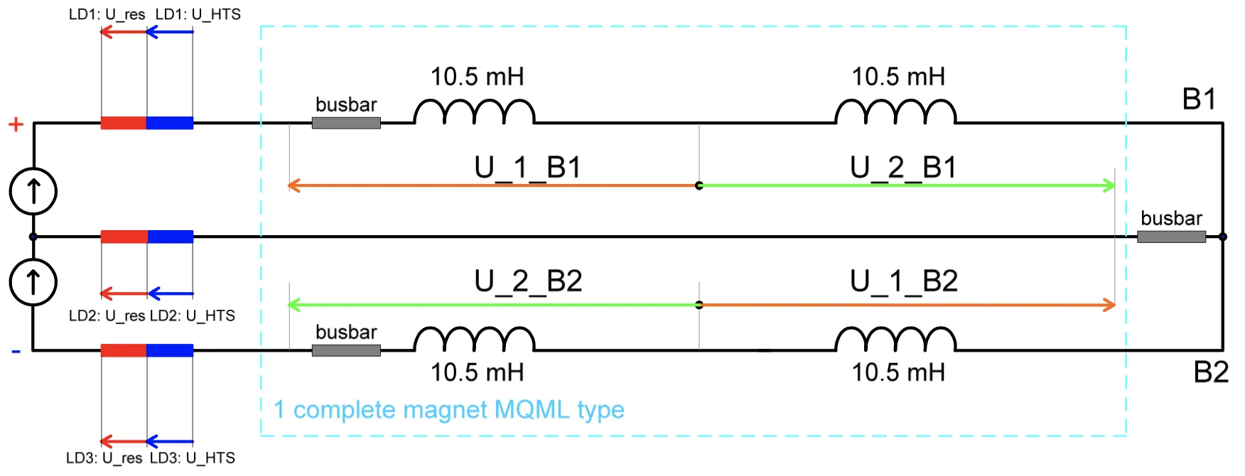
- 2MQML – long version
Apertures B1 of 2 magnets are powered in series with one power supply.
Apertures B2 of 2 magnets are powered in series with second power supply.
The return bus is common for both power circuits.
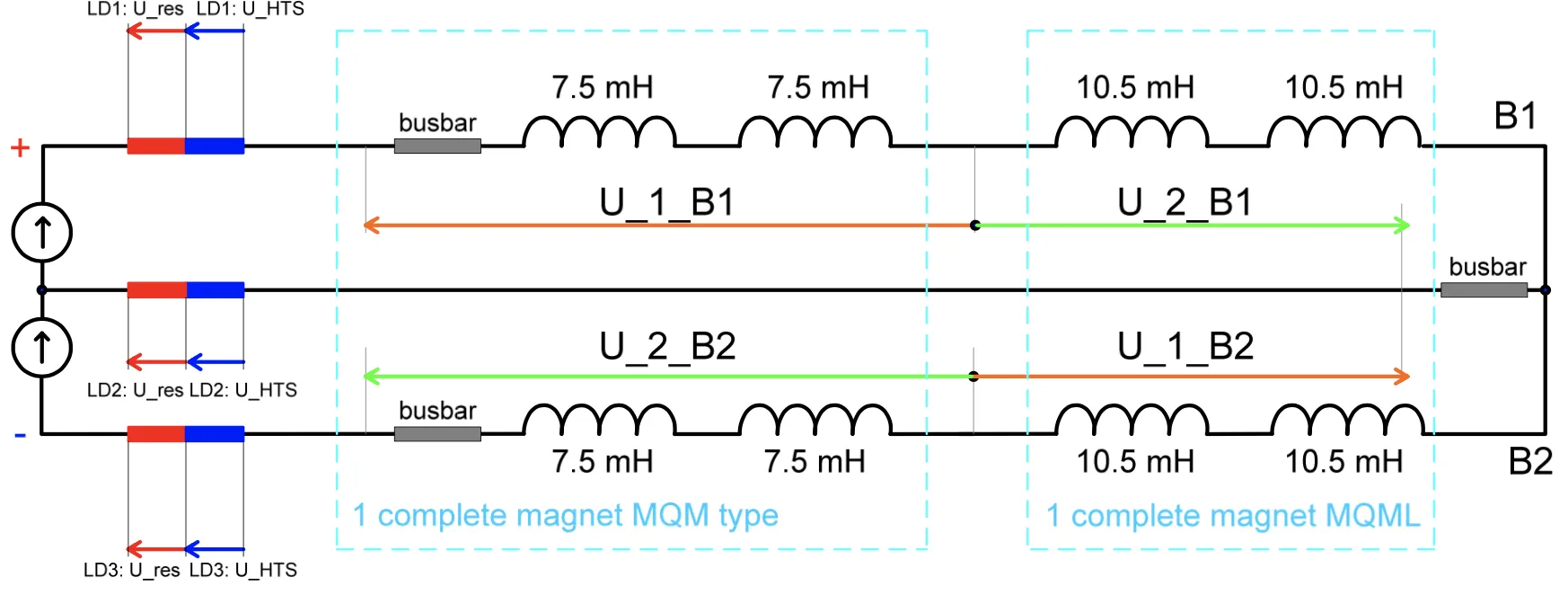
- 2MQM + 2MQML
Apertures B1 of 2 MQM and 2 MQML are powered in series with one power supply.
Apertures B2 of 2 MQM and 2 MQML are powered in series with second power supply.
The return bus is common for both power circuits.
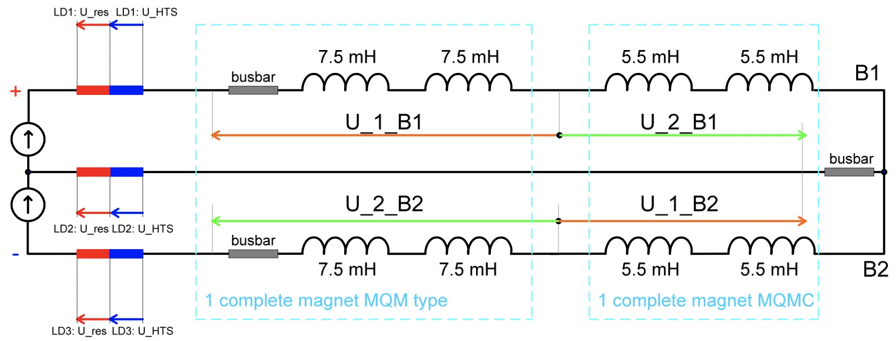
- 2MQM+2MQMC
Apertures B1 of 2 MQM and 2 MQMC are powered in series with one power supply.
Apertures B2 of 2 MQM and 2 MQMC are powered in series with second power supply.
The return bus is common for both power circuits.
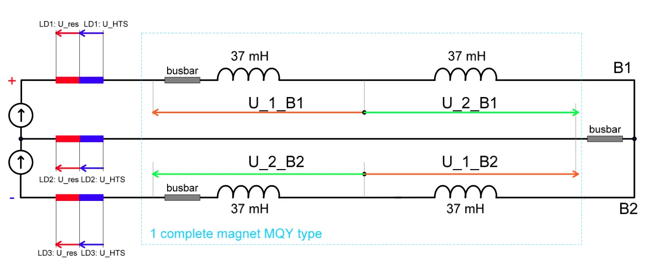
- 2MQY*
Apertures B1 of 2 magnets are powered in series with one power supply.
Apertures B2 of 2 magnets are powered in series with second power supply.
The return bus is common for both power circuits.
Note: * in accordance with layout database 2 MQY means apertures B1 and B2 of the one magnet MQY. type.
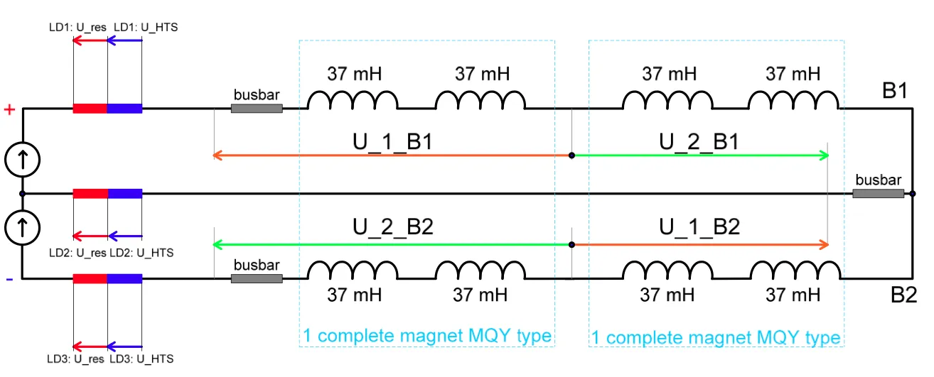
- 2x2MQY
Apertures B1 of 4 magnets are powered in series with one power supply.
Apertures B2 of 4 magnets are powered in series with second power supply.
The return bus is common for both power circuits.
| Type | Test | Current | Description | Notebook | Example report |
|---|---|---|---|---|---|
| HWC | PCC.3 | I_PCC | Power Converter Configuration | – | – |
| HWC | PIC2 | I_MIN_OP | Powering Interlock Controller check with standby current in the circuits. | AN_IPQ_PIC2 | AN_IPQ_PIC2 |
| HWC | PLI1.c3 | I_INJECTION | Fast Power Abort at injection current. | AN_IPQ_PLI1.c3 | AN_IPQ_PLI1.c3 |
| HWC | PLI2.f3 | I_INTERM_1 | Unbalanced ramp and Quench Heater Firing | AN_IPQ_PLI2.f3 | AN_IPQ_PLI2.f3 |
| HWC | PLI2.e3 | I_INTERM_1 | Unbalanced slow power abort | AN_IPQ_PLI2.e3 | AN_IPQ_PLI2.e3 |
| HWC | PNO.f4 | I_PNO | Symmetric Ramp and Symmetric Quench Heater Firing | ||
| HWC | PNO.a7 | I_PNO+I_DELTA | Powering to I_PNO + I_DELTA and unbalanced SPA | AN_IPQ_PNO.a7 | AN_IPQ_PNO.a7 |
| HWC | PNO.c4 | I_PNO | Current Lead test and FPA from I_PNO | AN_IPQ_PNO.c4 | AN_IPQ_PNO.c4 |
| Operation | FPA | I_PNO | FPA during operation with magnets quenching | AN_IPQ_FPA | AN_IPQ_FPA |
5. IPD (Individually Powered Dipoles) – Beam Separation Dipoles D1-D4
- MBX – D1
Single aperture of the magnet powered with one power supply.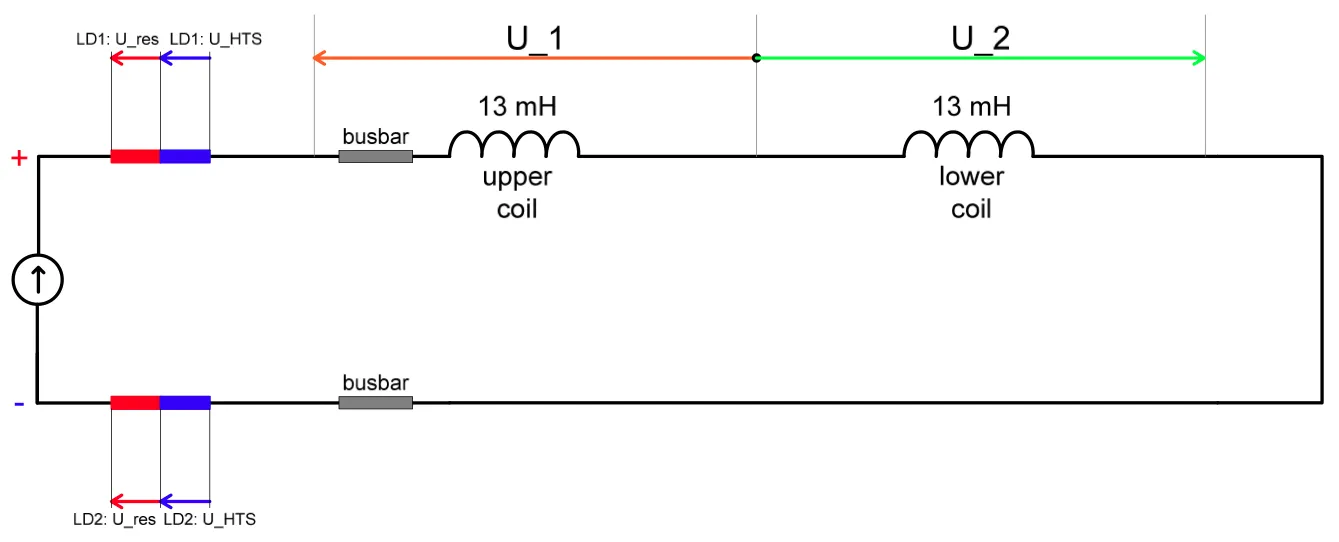
- MBRC – D2 – MBRB – D4
Apertures B1 and B2 of the magnet are powered in series with one power supply.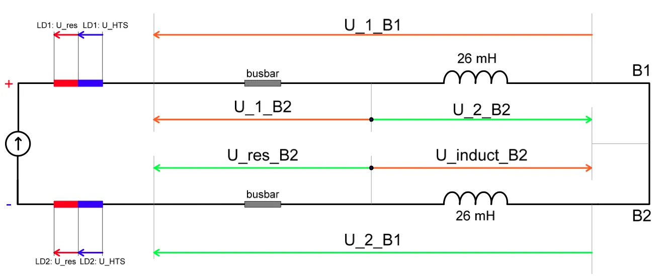
- MBRS – D3
Apertures B1 and B2 of the magnet are powered in series with one power supply but series connection done in the DFBA.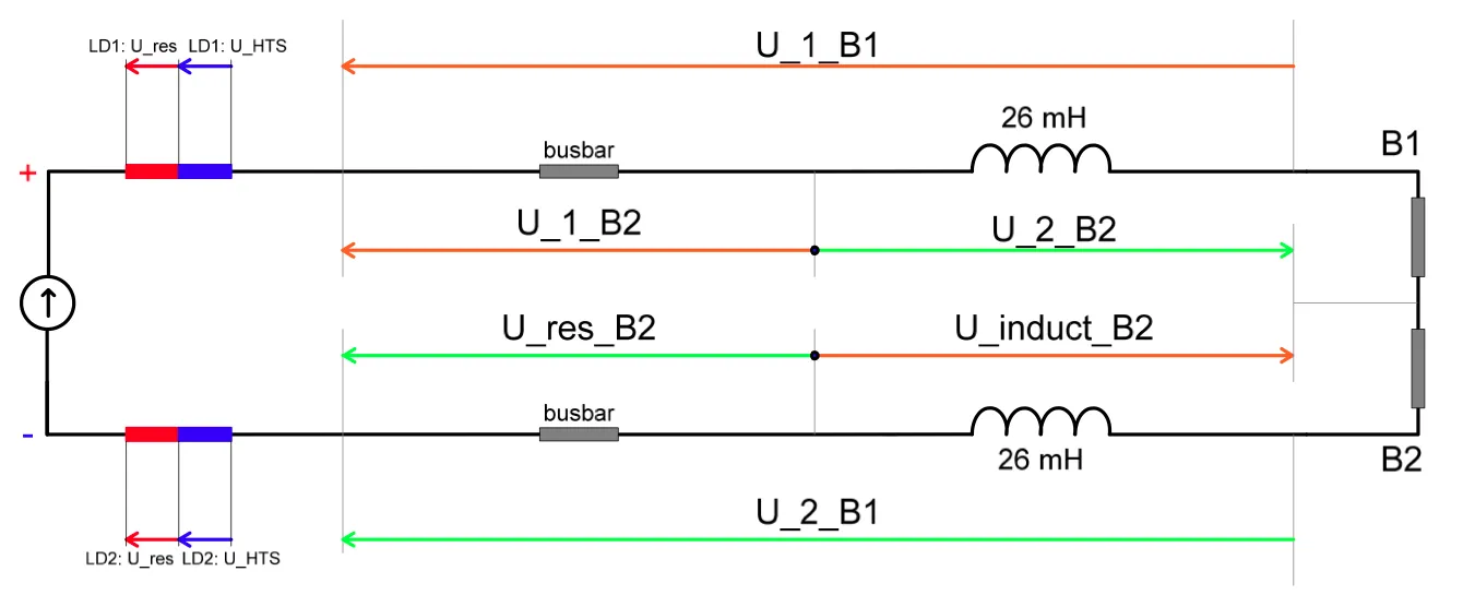
| Type | Test | Current | Description | Notebook | Example report |
|---|---|---|---|---|---|
| HWC | PCC.3 | I_PCC | Power Converter Configuration 1Q: Calibration of the PC | – | – |
| HWC | PIC2 | I_MIN_OP | Powering Interlock Controller check with standby current in the circuits. | AN_IPD_PIC2 | AN_IPD_PIC2 |
| HWC | PLI1.f2 | I_INJECTION | Fast Power Abort at injection current. | AN_IPD_PLI1.c2 | AN_IPD_PLI1.c2 |
| HWC | PLI2.f2 | I_INTERM_1 | Heater Provoked Quench | AN_IPD_PLI2.f2 | AN_IPD_PLI2.f2 |
| HWC | PLI3.c5 | I_INTERM_3 | Measurement of splice resistance and Fast Power Abort at intermediate current | AN_IPD_PLI3.c5 | AN_IPD_PLI3.c5 |
| HWC | PNO.a8 | I_PNO+I_DELTA | Powering to I_PNO + I_DELTA | AN_IPD_PNO.a8 | AN_IPD_PNO.a8 |
| HWC | PNO.c6 | I_PNO | Fast Power Abort at Nominal Current and Lead Test | AN_IPD_PNO.c6 | AN_IPD_PNO.c6 |
| Operation | FPA | I_PNO | FPA during operation with magnets quenching | AN_IPD_FPA | AN_IPD_FPA |
source: Test Procedure and Acceptance Criteria for the Separation Dipoles Circuits, MP3 Procedure, https://edms.cern.ch/document/874885/4.1
5. 600 A Circuits
The 600-A circuits come in one of two main variants:
- circuits with EE
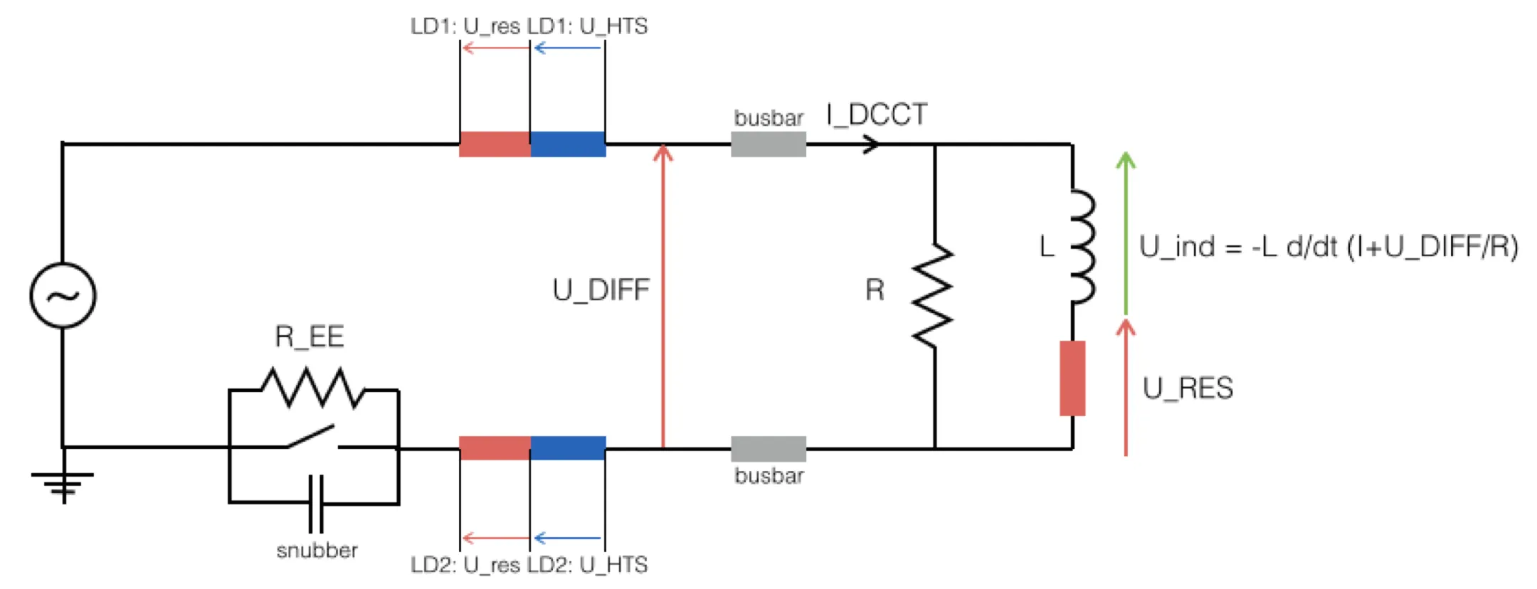
- circuits without EE
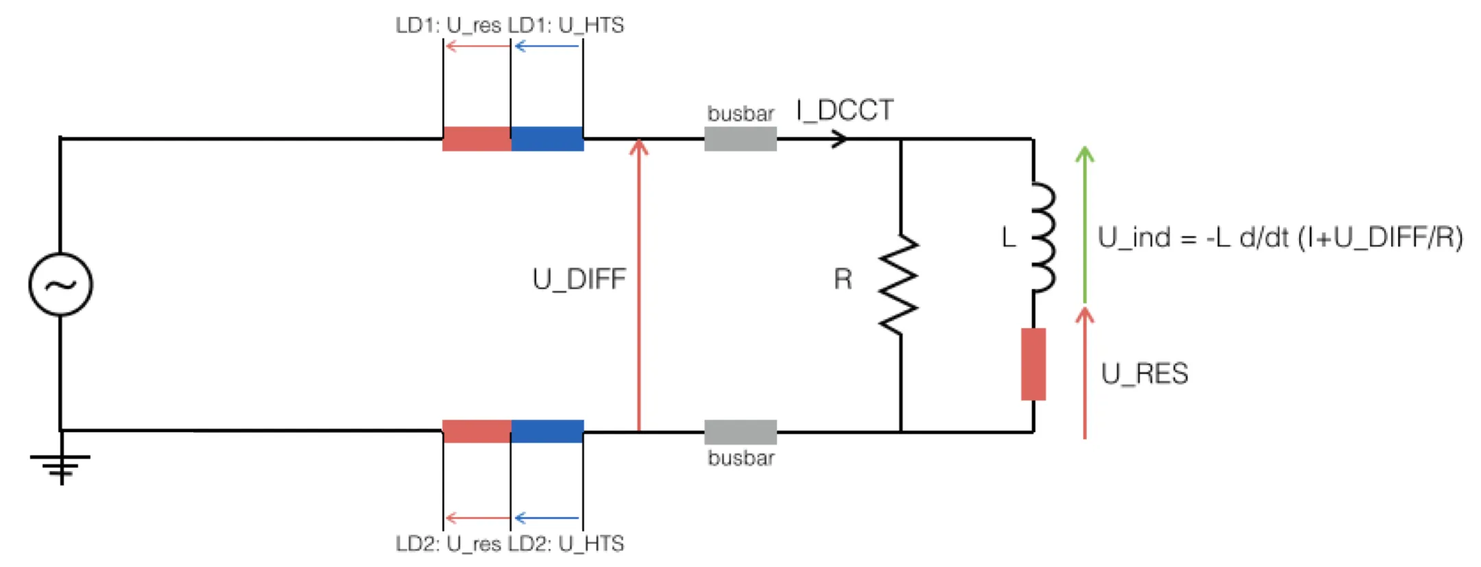
source: Test Procedure and Acceptance Criteria for the 600 A Circuits, MP3 Procedure, https://edms.cern.ch/document/874716/5.3
| Type | Test | Current | Description | Notebook | Example report |
|---|---|---|---|---|---|
| Operation | FPA | I_PNO | FPA during operation with magnets quenching | AN_600A_with_without_EE_FPA | AN_600A_with_without_EE_FPA |
| Operation | FPA | I_PNO | FPA during operation with magnets quenching | AN_600A_RCDO_FPA | AN_600A_RCDO_FPA |
| Operation | FPA | I_PNO | FPA during operation with magnets quenching | AN_600A_RCBXHV_FPA | AN_600A_RCBXHV_FPA |
6. 80-120 A Circuits
| Type | Test | Current | Description | Notebook | Example report |
|---|---|---|---|---|---|
| Operation | FPA | I_PNO | FPA during operation with magnets quenching | AN_60A_FPA | AN_60A_FPA |
7. 60 A Circuits
| Type | Test | Current | Description | Notebook | Example report |
|---|---|---|---|---|---|
| Operation | FPA | I_PNO | FPA during operation with magnets quenching | AN_80-120A_FPA | AN_80-120A_FPA |