Circuits
Every superconducting circuit family goes through its own sequence of powering tests. The tables below list those tests and what analyses them today.
Automated means SigMon analyses the test itself and returns a result to AccTesting; the code in brackets is the analysis that does it. Notebook means the analysis is still the legacy Jupyter notebook in lhc-sm-hwc, run by hand. Several tests share one analysis: the PXX analyses cover a whole family of tests that differ only in target current and trigger source.
Quench heater discharge analysis is not automated yet — it is run from a notebook, like the tests marked Notebook .
Type says when an analysis runs. HWC tests are part of a commissioning campaign; Operation analyses run on events during a run; Event analyses are triggered by a Post Mortem event rather than by a scheduled test.
To see the analyses actually running, look at the pipeline on the analysis repository, or browse generated reports at sigmon-reports.web.cern.ch .
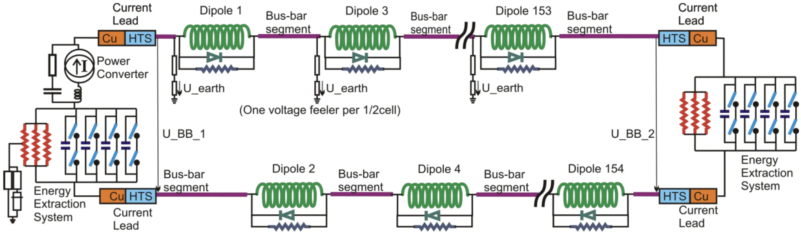
RB – Main Dipole Circuit
The RB main dipole circuit. Test Type What it verifies Analysis PCC.2HWC PC configuration Automated: PCC.2PIC2HWC Interlock paths via QPS and PIC Automated: PIC2PLI1.a2HWC Current cycle to I_INJECTION Notebook: AN_RB_PLI1.a2 PLI1.b2HWC Energy extraction from QPS Automated: PXX.B2PLI1.d2HWC Unipolar powering failure Automated: PXX.D2PLI2.s1HWC Splice mapping Automated: PLI2.s1PLI2.e2HWC Slow power abort Automated: PLI2.e2PLI2.b2HWC Energy extraction from QPS Automated: PXX.B2PLI2.f1HWC Heater provoked quench Notebook: AN_RB_PLI2.f1 PLIM.b2HWC Energy extraction, FPA via PIC Automated: PXX.B2PLIS.s2HWC Splice mapping at I_SM Automated: PLIS.s2PLI3.a5HWC Current cycle to I_INTERM_2 Automated: PLI3.a5PLI3.d2HWC Unipolar powering failure Automated: PXX.D2PNO.b2HWC Energy extraction from QPS Automated: PXX.B2PNO.a6HWC Current cycle to I_PNO Automated: PNO.a6FPAOperation FPA during operation, magnets quenching Notebook: AN_RB_FPA Quench heater dischargeEvent Discharge decay time and initial values, against a stored reference. Notebook: HWC_voltage_current_QHDA Energy extraction, 13 kAEvent Paired ODD/EVEN or RQF/RQD: peak voltages, decay constant, event time difference. Automated: lhc-sm-ee
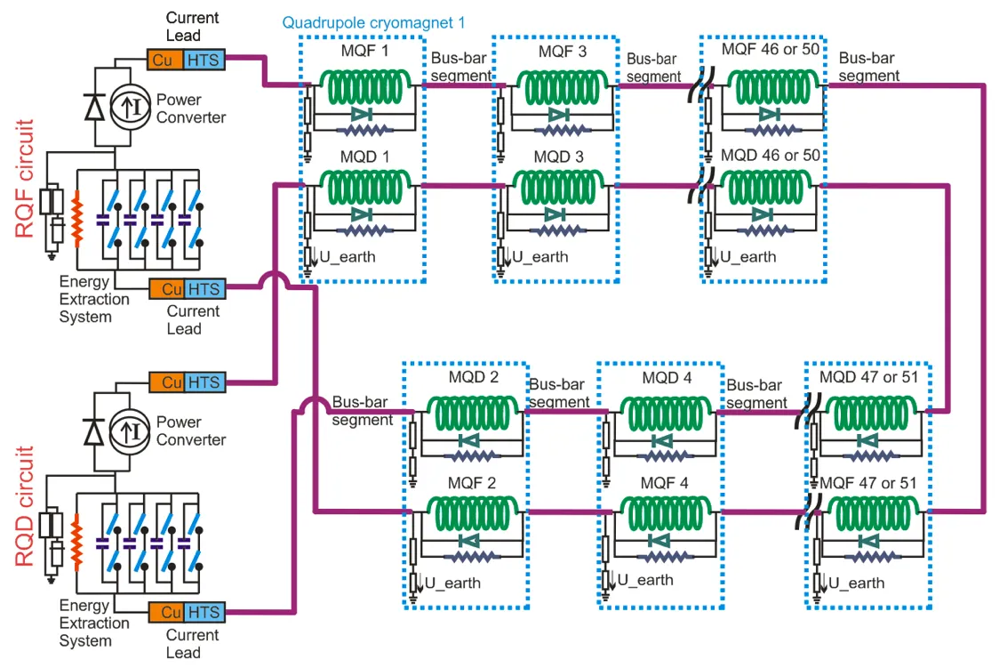
RQ – Main Quadrupole Circuit
The RQ main quadrupole circuit, RQD and RQF powered together. Test Type What it verifies Analysis PCC.3HWC PC configuration Automated: PCC.3PIC2HWC Interlock paths via QPS and PIC Automated: PIC2PLI1.b3HWC Energy extraction from QDS Automated: PXX.b3PLI1.d2HWC Unipolar powering failure Automated: PLI1.d2PLI2.s1HWC Splice mapping Automated: PLI2.s1PLI2.e2HWC Slow power abort Automated: PLI2.e2PLI2.b3HWC Energy extraction from QDS Automated: PXX.b3PLI2.f1HWC Heater provoked quench Notebook: AN_RQ_PLI2.f1 PLIM.b3HWC Energy extraction from QDS Automated: PXX.b3PLIS.s2HWC Splice mapping at I_SM Automated: PLIS.s2PLI3.a5HWC Current cycle to I_INTERM_2 Automated: PLI3.a5PLI3.b3HWC Energy extraction from QDS Automated: PXX.b3PNO.b3HWC Energy extraction from QDS Automated: PXX.b3PNO.a6HWC Current cycle to I_PNO Automated: PNO.a6FPAOperation FPA during operation, magnets quenching Notebook: AN_RQ_FPA Quench heater dischargeEvent Discharge decay time and initial values, against a stored reference. Notebook: HWC_voltage_current_QHDA Energy extraction, 13 kAEvent Paired ODD/EVEN or RQF/RQD: peak voltages, decay constant, event time difference. Automated: lhc-sm-ee
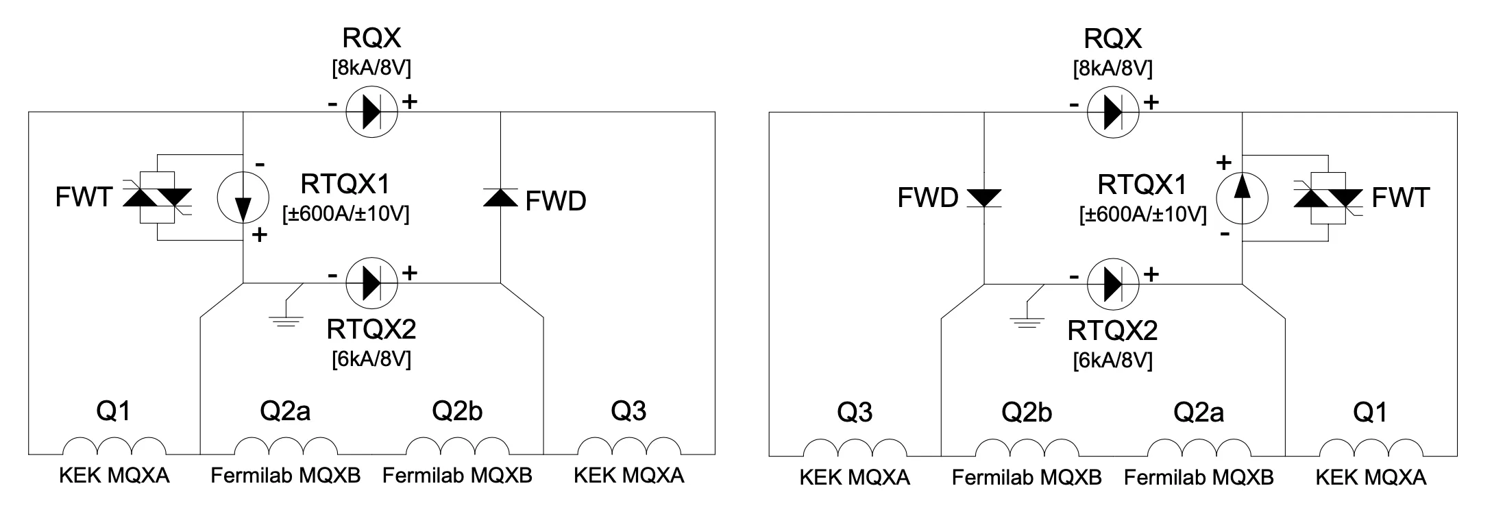
IT – Inner Triplet Circuits
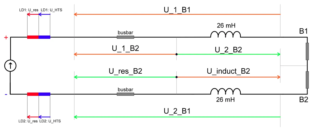
An inner triplet circuit. Test Type What it verifies Analysis PCC.T4HWC PC configuration, three converters Automated: PCC.T4PIC2HWC Interlock paths via QPS and PIC Automated: PIC2PNO.d12HWC PC failure, all at +10% Automated: PNO.d1xPNO.d13HWC PC failure, RTQX1 at -10% Automated: PNO.d1xPLI3.f6HWC Heater provoked quench Automated: PLI3.f6PNO.d14HWC PC failure, all at +50% Automated: PNO.d1xPNO.d15HWC PC failure at -50% Automated: PNO.d1xPNO.a9HWC Powering to I_PNO + I_DELTA Automated: PNO.a9PNO.d16HWC PC failure, all at +90% Automated: PNO.d1xPNO.d17HWC PC failure at -90% Automated: PNO.d1xFPAOperation FPA during operation, magnets quenching Notebook: AN_IT_FPA Quench heater dischargeEvent Discharge decay time and initial values, against a stored reference. Notebook: HWC_voltage_QHDA
IPQ – Individually Powered Quadrupoles
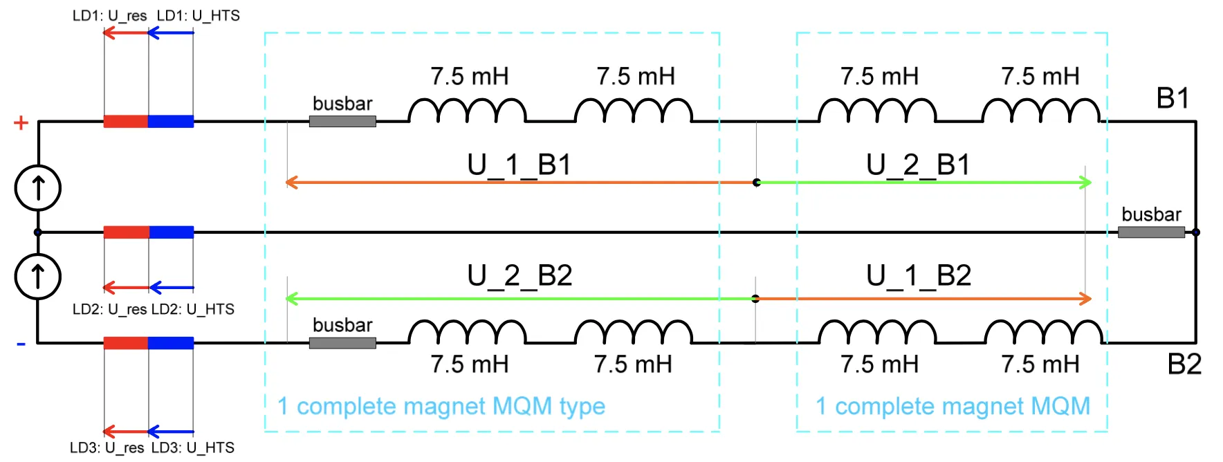
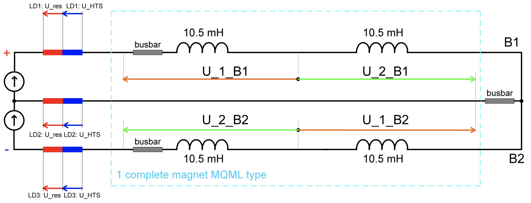
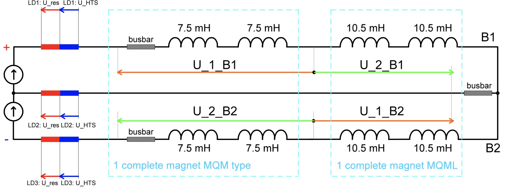
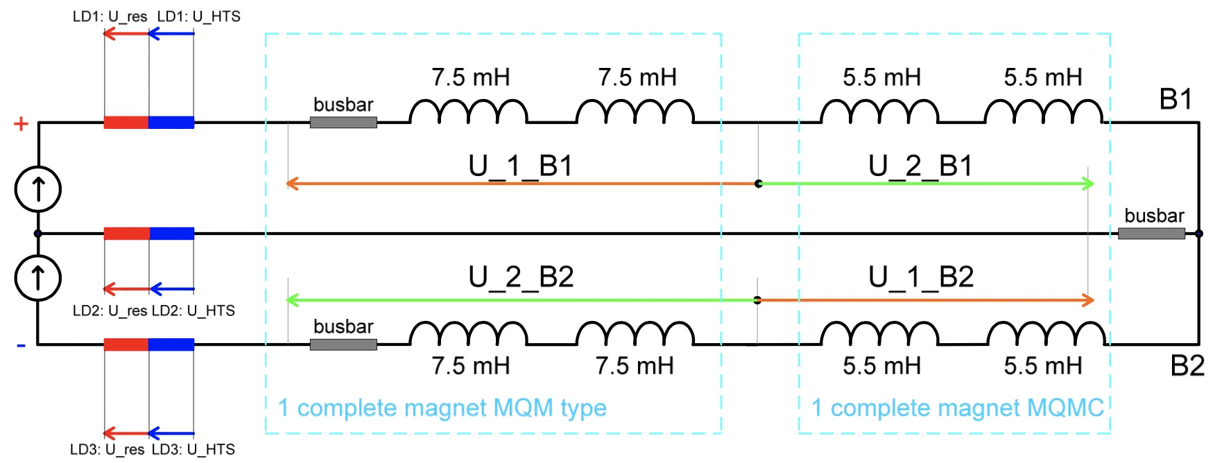
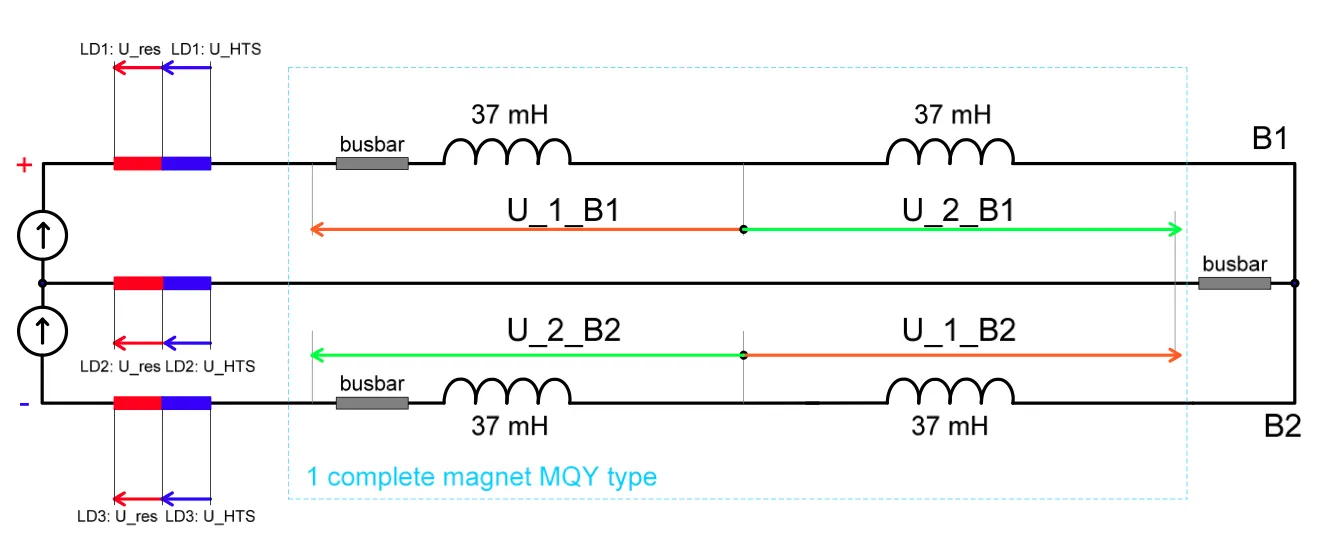
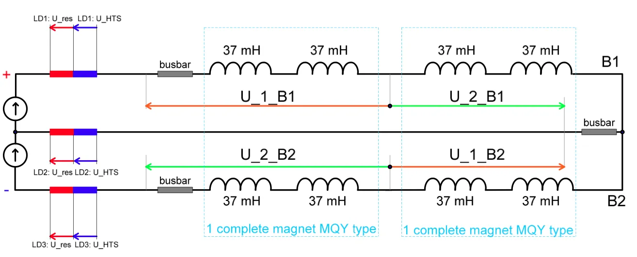
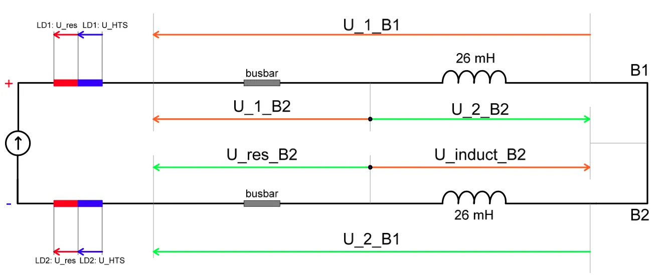
2MQM 2x2MQM 2MQML 2MQM and 2MQML 2MQM and 2MQMC 2MQY 2x2MQY Test Type What it verifies Analysis PCC.4HWC PC configuration, 1Q Automated: PCC.4PIC2HWC Interlock paths via QPS and PIC Automated: PIC2PLI1.c3HWC FPA at injection current Automated: PLI1.c3PLI2.f3HWC Unbalanced ramp, heater provoked quench Automated: PLI2.f3PLI2.e3HWC Unbalanced slow power abort Automated: PLI2.e3PNO.f4HWC Symmetric ramp and symmetric quench heater firing — PNO.a7HWC Powering to I_PNO + I_DELTA, unbalanced SPA Automated: PNO.a7PNO.c4HWC Current lead test and FPA Automated: PNO.c4FPAOperation FPA during operation, magnets quenching Notebook: AN_IPQ_FPA Quench heater dischargeEvent Discharge decay time and initial values, against a stored reference. Notebook: HWC_voltage_QHDA
IPD – Individually Powered Dipoles (beam separation dipoles)
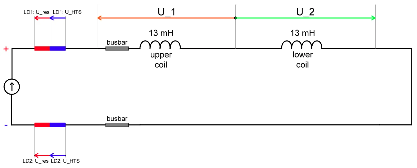
D1 – MBX D2 – MBRC and D4 – MBRB D3 – MBRS Test Type What it verifies Analysis PCC.3HWC PC configuration, 1Q Automated: PCC.3PIC2HWC Interlock paths via QPS and PIC Automated: PIC2PLI1.c2HWC FPA at injection current Automated: PLI1.c2PLI2.f2HWC Heater provoked quench Automated: PLI2.f2PLI3.c5HWC Splice resistance and FPA Automated: PLI3.c5PNO.a8HWC Powering to I_PNO + I_DELTA Automated: PNO.a8PNO.c6HWC Current lead test and FPA at nominal current Automated: PNO.c6FPAOperation FPA during operation, magnets quenching Notebook: AN_IPD_FPA Quench heater dischargeEvent Discharge decay time and initial values, against a stored reference. Notebook: HWC_voltage_QHDA
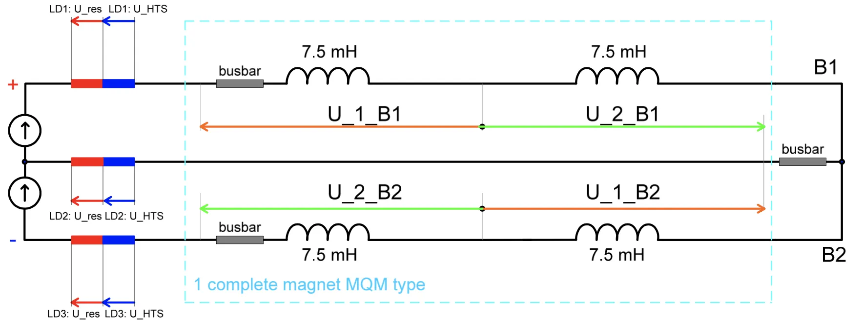
600 A Circuits
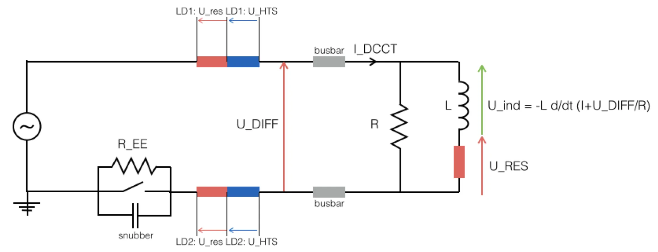
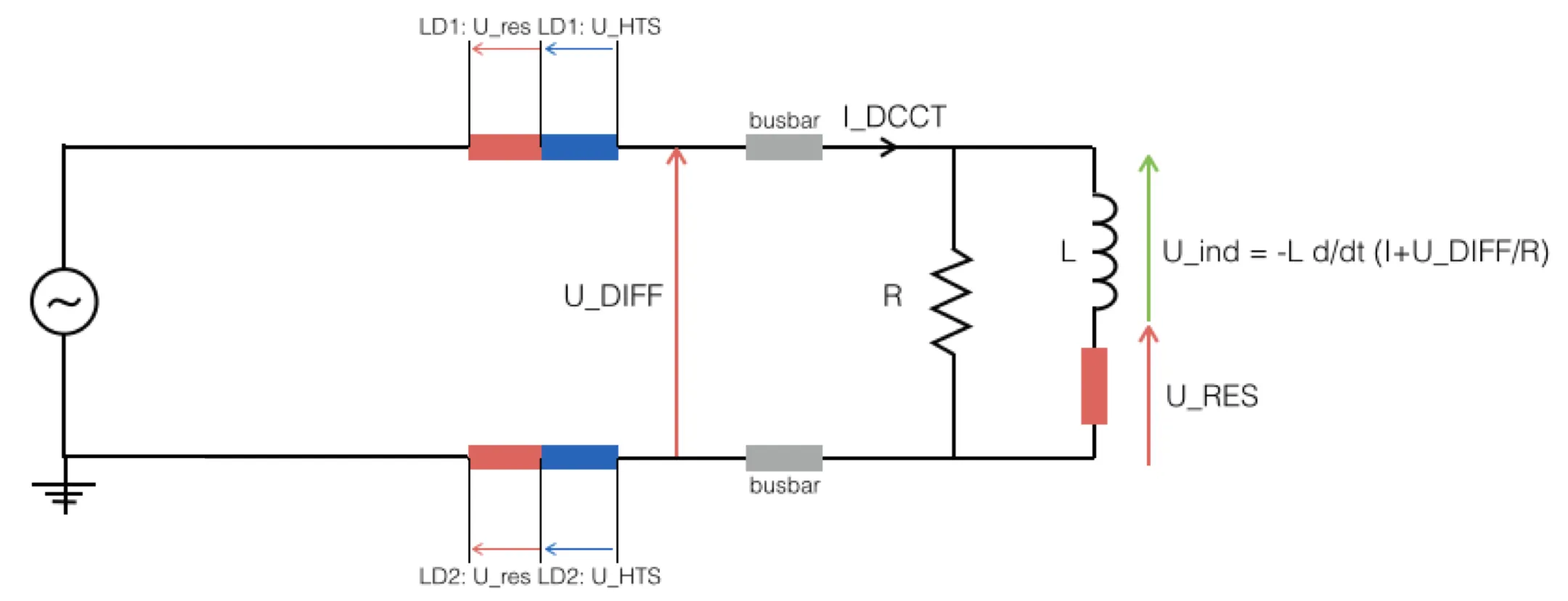
A 600 A circuit with energy extraction. A 600 A circuit without energy extraction. Test Type What it verifies Analysis PCC.5HWC PC configuration, 4Q Automated: PCC.5PIC2HWC Interlock paths via QPS and PIC Automated: PIC2PCS, PNO.a3HWC Bipolar cycle Automated: PCS and PNO.a3PLI3.b1HWC Energy extraction from QPS Automated: PLI3.b1PNO.b1HWC Energy extraction from QDS Automated: PNO.b1PNO.d3HWC Bipolar powering failure Automated: PNO.d3PNO.x1HWC Combined powering for RCBXH / RCBXV Automated: PNO.x1PNO.x2HWC Combined powering for RCO / RCD Automated: PNO.x2FPAOperation FPA, with and without EE Notebook: AN_600A_FPA FPAOperation FPA, RCDO circuits Notebook: AN_600A_RCDO_FPA FPAOperation FPA, RCBXH / RCBXV circuits Notebook: AN_600A_RCBXHV_FPA Energy extraction, 600 AEvent Switch opening failure, capacitor voltages, end-of-decay current and peak voltages. Automated: lhc-sm-ee
80-120 A Circuits
Test Type What it verifies Analysis PCC.1HWC PC configuration, 4Q Automated: PCC.1PIC2HWC Powering failure via PIC Automated: PIC2PNO.a1HWC Bipolar cycle Automated: PNO.a1PNO.d1HWC Bipolar powering failure Automated: PNO.d1FPAOperation FPA during operation Notebook: AN_80-120A_FPA
60 A Circuits
Test Type What it verifies Analysis PCC.1HWC PC configuration, 4Q Automated: PCC.1PNO.a1HWC Bipolar cycle Automated: PNO.a1PNO.d1HWC Bipolar powering failure Automated: PNO.d1FPAOperation FPA during operation Notebook: AN_60A_FPA
Fast Power Abort analysis during operation is still served by the legacy notebooks listed in the tables above.